


From Passives to MOSFETs & GaN: Master SMPS Design Fundamentals
Release time:
2026-09-04 11:38
Source:


Switching‑Mode Power Supplies (SMPS), featuring compact size, light weight and high efficiency, are widely adopted in nearly all electronic devices. They represent an indispensable power‑supply solution for today’s fast‑growing electronic‑information industry.
Nevertheless, designing an SMPS is far from trivial. Its peripheral circuits are highly complex, employing a wide variety of components with diverse performance characteristics. Engineers new to SMPS development often feel overwhelmed when faced with lengthy bills‑of‑materials.
To build high‑performance switching‑mode power supplies, one must thoroughly understand the types and core functions of each component.
From a functional perspective, this article systematically reviews the classification and roles of common SMPS components, helping readers establish a complete component knowledge framework.

I. Two Major Component Categories: General‑Purpose and Special‑Purpose Components
Components used in SMPS peripheral circuits fall broadly into two groups: general‑purpose components and special‑purpose components.
General‑purpose components are the most fundamental building blocks, including resistors, capacitors, inductors, transformers and diodes. They form the core circuit skeleton of an SMPS.
Special‑purpose components comprise Fast‑Recovery Diodes (FRD), Transient‑Voltage‑Suppression diodes (TVS), Fuse Resistors (FR), Silicon‑Controlled Rectifiers (SCR), optocouplers and more. They typically execute dedicated tasks for protection, isolation or high‑performance power conversion.
Below we conduct an in‑depth analysis of each component type and its functions.
II. Resistors: The Unassuming yet Indispensable Circuit Workhorse
Resistors serve multiple functions within SMPS, appearing everywhere for voltage sampling, voltage division, current limiting and protection.
表格
| Resistor Type | Key Functions |
|---|---|
| Sampling Resistor | Forms output‑voltage sampling circuit; feeds sampled voltage to feedback circuitry |
| Voltage‑Equalizing Resistor | Balances voltage in symmetrical DC‑input circuits (also called balancing resistor) |
| Voltage‑Divider Resistor | Implements resistive voltage divider |
| Discharge Resistor | Releases residual charge stored in EMI‑filter capacitors upon power‑off |
| Current‑Limiting Resistor | Provides current‑limit protection for Zener diodes, optocouplers and input filter capacitors |
| Current‑Sense Resistor | Works with over‑current protection circuits to cap maximum output current |
| Minimum‑Load Resistor | Provides minimum loading required for stable SMPS operation; prevents excessive output voltage under open‑load conditions |
| Bias Resistor | Supplies bias voltage to control terminals or stabilizes transistor operating points |
| Protection Resistor | Used in RC snubber networks and V‑D‑R‑C clamping protection circuits |
| Damping Resistor | Suppresses circuit resonance |
Special‑function resistors are also widely used: Metal‑Oxide Varistors (MOV) and Thermistors (NTC / PTC). MOVs suppress transient over‑voltages: when voltage exceeds their threshold, their resistance drops sharply to shunt surge current and deliver lightning‑surge protection. NTC negative‑temperature‑coefficient thermistors are placed in series on the AC input. They exhibit high resistance at power‑on and effectively suppress inrush‑current spikes.

III. Capacitors: Multi‑Role Devices for Energy Storage, Filtering and Coupling
As common as resistors in SMPS, capacitors perform energy storage, filtering, coupling, decoupling and time‑delay functions.
表格
| Capacitor Type | Key Functions |
|---|---|
| Filter Capacitor | Builds input and output filter networks |
| Coupling Capacitor | Also known as DC‑blocking capacitor; blocks DC while passing AC signals |
| Decoupling Capacitor | Prevents circuit self‑oscillation |
| Soft‑Start Capacitor | Implements soft‑start circuits for gradual rise of output voltage and current |
| Compensation Capacitor | Forms RC frequency‑compensation networks |
| Speed‑Up Capacitor | Improves transistor switching speed |
| Oscillator Capacitor | Used in RC and LC oscillator topologies |
| Bootstrap Capacitor | Raises supply voltage for input stages or implements voltage feed‑forward circuits |
| Energy‑Storage Capacitor | Pump capacitors for polarity‑reversing DC‑DC converters |
| Noise‑Suppression Capacitor | Filters electrical noise interference |
Safety capacitors form a special subgroup: X‑capacitors and Y‑capacitors. X‑capacitors filter differential‑mode interference across power‑line conductors. Y‑capacitors provide return paths for interference currents coupled from the primary side to the secondary side, blocking such currents from flowing to ground through secondary‑side circuits. Both play irreplaceable roles within EMI filters.
Equivalent Series Resistance (ESR) is a critical selection parameter. MLCC ESR varies significantly with temperature, and capacitance degrades at high temperatures. For electrolytic capacitors, rated ripple current must exceed actual circuit ripple; otherwise service life will degrade drastically.

IV. Inductors & Common‑Mode Chokes: Magnetic Components for Filtering and Energy Storage
Inductors primarily handle filtering and energy‑storage tasks in SMPS.
表格
| Inductor Type | Key Functions |
|---|---|
| Filter Inductor | Constructs LC filter circuits |
| Energy‑Storage Inductor | Commonly used in buck and boost DC‑DC converters |
| Oscillator Inductor | Forms LC oscillator circuits |
| Common‑Mode Choke | Also called common‑mode inductor; suppresses common‑mode noise inside EMI filters |
| Differential‑Mode Inductor | Single‑winding component placed in series on input to attenuate differential‑mode noise |
The common‑mode choke is a core EMI‑filter element. Together with X‑ and Y‑capacitors, it forms the input filter network. It suppresses incoming electromagnetic noise and spurious signals, while also stopping high‑frequency noise generated by the power supply from polluting the mains grid.
When selecting inductors, pay close attention to saturation current: maintain at least 20 % derating margin. Core material selection matters: ferrites (e.g. PC40) deliver lower losses for high‑frequency operation (> 1 MHz); iron‑powder cores (e.g. CSD) offer superior saturation resistance for frequencies below 500 kHz.

V. Transformers: Core Devices for Galvanic Isolation and Voltage Conversion
Transformers enable voltage transformation and galvanic isolation in SMPS. Two main types are deployed:
- Line‑frequency transformer: Steps and isolates AC mains, feeding rectified‑filtered power to downstream DC‑DC converters.
- High‑frequency transformer: Stores energy, transforms voltage and provides isolation for transformer‑less SMPS topologies.
High‑frequency transformers are key to SMPS miniaturization: higher operating frequency yields smaller transformer size. Modern SMPS have pushed operating frequencies from tens of kilohertz up to hundreds of kilohertz and even megahertz, enabling substantial volume reduction.
VI. Diodes: Ubiquitous Semiconductor Switches for Rectification and Freewheeling
Diodes have extremely broad applications in SMPS, with a rich variety of device types.
表格
| Diode Type | Key Functions |
|---|---|
| Rectifier Diode | Low‑frequency or high‑frequency rectification |
| Freewheeling Diode | Typical in buck DC‑DC converters; provides discharge path for back‑EMF |
| Clamping Diode | Builds V‑D‑R‑C clamping circuits; absorbs voltage spikes to protect MOSFETs |
| Fast‑Recovery Diode (FRD) | Short reverse‑recovery time, suited for high‑frequency switching |
| Transient‑Voltage‑Suppression Diode (TVS) | Shunts transient surge voltages to protect downstream circuits |
| Schottky Diode | Near‑zero reverse‑recovery time for low‑voltage high‑frequency scenarios; typical maximum rating ≤ 40 V |
Reverse‑recovery time is a vital parameter for high‑frequency SMPS. Schottky diodes (near‑zero reverse recovery) are preferred for high‑frequency low‑voltage work. For high‑voltage inputs such as 220 VAC mains, fast‑recovery diodes with reverse‑recovery time below 50 ns are mandatory; otherwise switching losses will rise sharply.
VII. Power‑Switching Devices: MOSFETs, IGBTs and the Wide‑Band‑Gap‑Semiconductor Era
Power‑switching devices are the core actuators of SMPS. They perform high‑frequency on/off control and directly determine power‑supply efficiency and power density.
🔺 MOSFET — The Most Widely Used Power Switch Metal‑Oxide‑Semiconductor Field‑Effect Transistors (MOSFET) dominate SMPS power‑switch applications. Their non‑conductive gate yields very high input impedance; drain current is controlled by gate‑source voltage.
Two key parameters for component selection:
- On‑state resistance Rds(on): Directly governs conduction loss. Lower resistance at a given voltage rating yields higher efficiency.
- Gate charge Qg: Smaller Qg reduces drive losses in high‑frequency designs.
🔺 IGBT — Solution for High‑Voltage High‑Power Applications Insulated‑Gate Bipolar Transistors (IGBT) combine the high input impedance of MOSFETs with the low forward‑voltage drop of BJTs, making them suitable for high‑voltage, high‑power SMPS.
🔺 Wide‑Band‑Gap Semiconductors — The Rise of SiC and GaN Silicon‑Carbide (SiC) and Gallium‑Nitride (GaN) devices are rapidly penetrating SMPS markets. SiC MOSFETs serve mid‑to‑high‑power systems, widely deployed in AI servers and EV charging stations. Thanks to excellent high‑frequency low‑loss performance, GaN devices gain fast adoption in consumer electronics such as fast‑charge adapters. GaN‑based integrated converters cut switching losses and boost component integration, breaking power‑density limits of silicon‑based designs.

VIII. Control ICs and Optocouplers: The “Brain” and “Nerves” of Power Supplies
🔺 PWM Controller IC — SMPS Command Center The core control circuitry of SMPS is the Pulse‑Width‑Modulation (PWM) controller. PWM ICs stabilize output voltage by adjusting the duty cycle of power switches.
Today’s PWM controllers are highly integrated. For example, the NCP1380D, a high‑performance quasi‑resonant current‑mode PWM controller, is widely used in off‑line AC‑DC conversions, adapters and LED drivers. Digital power controllers further integrate ARM cores with dedicated analog front‑ends, enabling flexible control‑loop parameter tuning via firmware.
🔺 Optocoupler — Signal Bridge Across Isolation Barriers For SMPS requiring galvanic separation between input and output, optocouplers deliver feedback‑signal transmission across isolation boundaries.
Optocouplers convert electrical signals to light and back to electrical signals to achieve galvanic isolation. Within isolated feedback loops, optocouplers commonly pair with the TL431 precision adjustable shunt regulator. TL431 acts as an external error amplifier, while the optocoupler transmits error signals across the isolation barrier to the primary‑side PWM controller. This closed‑loop feedback maintains stable output voltage under varying load and input conditions.
IX. Protection Components: Safeguarding Power‑Supply Reliability
Protection components are essential. They ensure safe shutdown under fault conditions, protecting both the power supply itself and connected loads.
表格
| Protection Component | Key Functions |
|---|---|
| Fuse | Placed in series at power input; melts under over‑current to protect downstream circuits |
| Metal‑Oxide Varistor (MOV) | Suppresses transient over‑voltages; lightning‑surge protection |
| NTC Thermistor | Suppresses power‑on inrush current |
| TVS Diode | Shunts external voltage‑surge transients |
SMPS auxiliary circuits further incorporate input over‑/under‑voltage protection, output over‑/under‑voltage protection, output over‑current protection and output short‑circuit protection. Together these mechanisms build a complete safety system.
Closing Remarks: From Component Understanding to Practical Power‑Supply Design
From basic resistors and capacitors, through main‑power MOSFETs, to emerging SiC and GaN devices — every SMPS component fulfills an irreplaceable role.
For power‑supply engineers, recognizing component types and functions is only the starting point. More critical is making sensible component selection and layout decisions, considering topology, power rating, operating frequency and cost constraints.
SMPS design is far more than “changing voltage levels”. It represents a systematic engineering discipline drawing on electromagnetics, thermodynamics, material science and control theory. And everything starts with deep understanding of individual components.
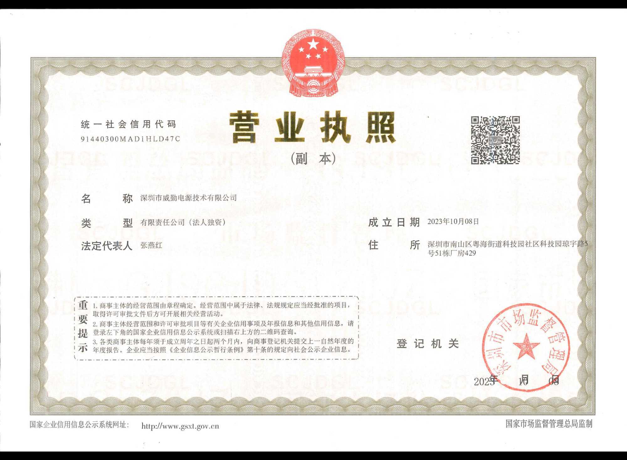
From Theory to Practice: WINCHEN Power Approach to Switching‑Mode Power Supplies
Once component theory is mastered, the next question becomes: how do we translate that knowledge into reliable products? Shenzhen Winchen power Technology Co., Ltd. is exactly such a practitioner.
As a national high‑tech enterprise integrating electronic‑product R&D, production and sales, Winchen Power delivers complete solutions for full‑range PoE products as well as AC‑DC / DC‑DC module power supplies.

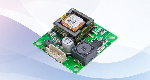
Its product portfolio includes PoE modules, isolated AC‑DC / DC‑DC power modules, isolated communication modules, bare‑board SMPS, enclosed SMPS, industrial DIN‑rail power supplies, and specialized power units for photovoltaic and energy‑storage applications. Winchen power products illustrate the full chain from theoretical component principles to real‑world engineering implementation:
- Topology selection: Winchen power modules adopt advanced LLC resonant topology and synchronous‑rectification technology, routinely achieving efficiencies above 90 %‑95 %. The LLC resonant converter, a mainstream DC‑DC topology, leverages ZVS / ZCS characteristics to drastically reduce switching losses.
- Wide‑band‑gap device adoption: High‑frequency design achieves high power density, delivering greater power within smaller form factors, consistent with the SiC / GaN wide‑band‑gap semiconductor trend.
- Comprehensive protection‑component implementation: Built‑in multi‑layer protection including over‑current, over‑voltage, short‑circuit and over‑temperature protection — real‑world realization of the protection‑component principles described above.
- Careful EMI‑component engineering: On‑board EMI filters meet international standards such as CISPR 32 / EN 55032 Class B with low conducted and radiated emissions, demonstrating precise coordination among X‑capacitors, Y‑capacitors and common‑mode chokes.
- Wide‑input‑range and industrial‑grade component selection: AC‑DC units support 85‑305 VAC wide‑range input; DC‑DC versions cover complex voltage scenarios such as 9‑36 VDC and 18‑75 VDC. Critical components use military‑grade specifications with ample design margins.
- Rigorous quality validation: Full‑automatic SMT assembly plus 100 % high‑temperature full‑load burn‑in testing ensures every component is fully validated before shipment.
Winchen power products are widely deployed across industrial control, new‑energy systems, charging stations, power equipment, rail transit, network communications, smart home, instrumentation, smart city, smart healthcare and IoT terminals. At the 2026 Munich Electronics Show in Shanghai, customers paid great attention to the modules’ compact packaging, high power density, wide input‑voltage range, high‑efficiency conversion and comprehensive protection features.
These strengths stem directly from well‑considered component choices and design decisions, collectively forming core product competitiveness.
Developing reliable, high‑efficiency switching‑mode power supplies from basic resistors and capacitors requires precisely the kind of accumulated expertise and engineering practice that WQ Power has built over more than a decade.

More news
2026 Complete Guide: How to Select a Reliable Isolated Power Module
This 2026 updated guide covers core functions, classification, selection best practices, and reliability standards for isolated power modules. Drawing on 12 years of manufacturing experience from Winchen Power, we share real test data and answer the most common questions to help you pick the right module for your project.
Complete 2026 Guide to Isolated Power Module: Selection, Specs & Applications
This 2026 practical guide draws on over 12 years of manufacturing experience from Shenzhen Winchen Power to explain all key details of isolated power modules. It covers core definitions, critical specs, step-by-step selection, common applications, and troubleshooting, helping engineers, product designers and procurement teams make informed decisions and avoid costly mistakes.
2026 Complete Guide: Isolated Power Module Selection, Benefits & Top Solutions
This 2026 comprehensive guide to isolated power modules is designed for design engineers and procurement teams. We draw on over 15 years of manufacturing and testing experience from Shenzhen Winchen Power to explain core functions, selection criteria, application scenarios, and industry standards, helping you select the right isolated power module for your project.
2026 Complete Guide to Isolated Power Modules: Selection, Benefits & Best Practices
This 2026 guide from Winchen Power’s engineering team breaks down everything you need to know about isolated power modules, from core definitions to application scenarios, selection criteria, and maintenance. We draw on 15+ years of manufacturing experience and third-party test data to deliver unbiased, actionable insights for engineers and procurement managers.

Hotline
+86-755-83576347
Address: 13th Floor, Building 4, Kelu Smart Energy Industrial Park, Guangming District, Shenzhen
Mobile:86182 1836 5403
E-mail:alan@winchenpower.com

Focus on us
© 2024 Shenzhen Winchen Power Technology Co., Ltd.